Relic from the Past - VHS Camcorder
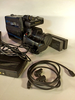
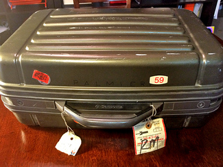 There are also some videos lurking in a box somewhere of several model railroads, including Lou Shultz's C&O Atticgheney Subdivision as well as the Crescent City Model Railroad Club. My mother reminded me that she still had the video camera responsible for these tapes safely tucked away. My grandfather, Michèle Palmieri, bought this camera in the late 1980's for family videos. Of course, this camera quickly got pressed into railfan photography! Tragically my grandfather passed away in 1992, however, the camera continued to serve for many years. The camera was still in the Samsonite case that protected it during my travels. Stickers for Amtrak trains 59, 21, and 5 decorate the shell as well as a couple of stubs from Amtrak claim checks and an Address Tag. Inside, were the camera, four batteries, and the charger. Hidden underneath the foam padding were some more cables and a pile of Amtrak head-end passes issued to me when I was an intern for Amtrak in New Orleans. Included was a head end pass for train No. 21 between Chicago and Fort Worth in February of 1998. It was on this trip that I interviewed for a Train Dispatcher position with the BNSF. The rest, as they say, is history! Now it is time to take the next step and start digitizing these videos and uploading them to YouTube. I will be doing some research to determine what equipment and software will yield the highest quality digital files of these VHS movies. Chris
0 Comments
Paint Booth Painted and Assembled
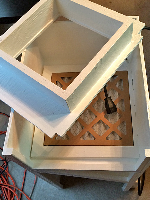
Several cans of primer and house paint left over from previous home projects were used so I did not have to spend any money for paint. First I finished up a can of white primer on all of the components. This took a couple of days to get all of the sides and angles covered. Next, I had a half can of white semi-gloss paint which I applied to all of the components in the same manner. I choose white to intensify the lighting inside the painting chamber and to create a non-biased lighting effect on the objects being painted. The paint was a little old and thick, but worked just fine. I like the heavy utilitarian look. All of the electrical wires and components were sealed with silicone before painting. The thick paint was sufficient enough to cover all of the silicone which has a repellent property to thinner paint. 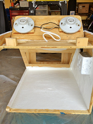 I debated the pros and cons of taking apart the light box and decided to go ahead and disassemble it to paint the inside. The light box sits on top of the front of the painting chamber and serves as an external housing for the porcelain light fixtures for two light bulbs. This takes the wiring and the fixtures out of the painting chamber so that the bulbs are out of the way of the painting process. The porcelain fixtures are mounted upside-down on raised legs on the top panel. It was necessary to put these legs on to allow the wiring access to the fixtures. Of note, the top panel of the light box is cut just a little smaller than the frame it sits in. Also, the two holes in the roof of the painting chamber are cut a little larger than the porcelain light fixtures. The purpose of this is to allow air to flow into the light box from the outside and then into the painting chamber at the base of the light bulbs. When the Paint Booth vent is turned on external air will flow from the inside of the light box into the painting chamber and then into the vent at the back of the paint booth. This current serves two purposes. First it creates a natural cooling airflow around the light bulbs which do generate some heat. Second this flow will carry any lingering vapors in the painting chamber away from the bulbs ensuring that there is not a buildup of flammable vapor around the bulbs. 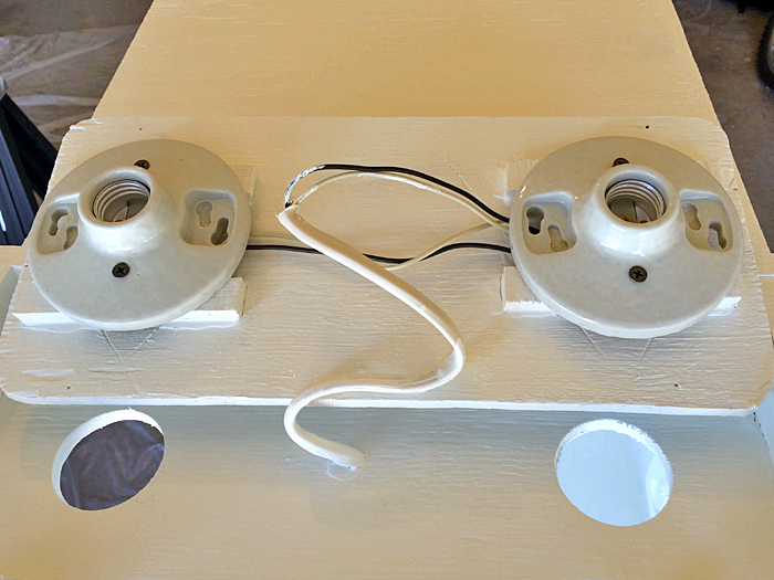 The below slideshow consists of a number of images of the components during this painting process. I did take the time to mask certain things like the switches, outlet, light fixtures and plugs. Four saw horses were placed over a tarp in the garage for painting. Two saw horses supported the main body of the paint booth. Two surplus wooden dowels (thanks to Elfa sales at the Container Store over the years) were placed across the remaining two saw horses to support the other components while being painted. After several days of painting and drying the components were brought inside for reassembly. All of the items fit nicely, though I did need to sand the edges of the reduction chamber as the paint made it to big to seat properly. The first item re-installed was the white air intake grill at the bottom rear of the painting chamber. Six small screws hold this in place. As it came in a white color, this component was not painted. Next the paint booth was stood on-end and the filter, reduction chamber, and fan housing were inserted and screwed in place from the rear.
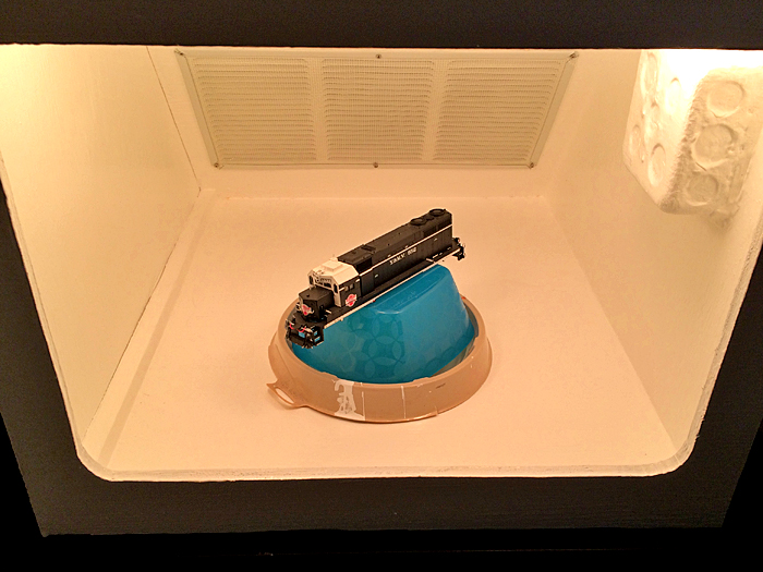
The light switch cover went on next and then the open side panels were screwed into place. The very last thing, of course, was to put in the light bulbs. Plugged in, the lights, fan, and auxiliary switch and socket worked flawlessly. I still have to select, order, and install a turntable for the painting chamber. To test the final effect, I used a paint can drip container and a plastic bowl to simulate the turntable and used the shell of my Y&MV SD35 552 to pose for the below shots: The paint booth project is almost over as just a few things are needed to place it in service. The vent block that will fit into a window frame needs to be constructed and I still need to buy the dryer ducting to connect the fan vent outlet to the window vent block. As painting projects are undertaken and the paint booth gets some use, I am sure mods to make it more user friendly will become evident. Those updates will be posted in this blog labeled with the Paint Booth category.
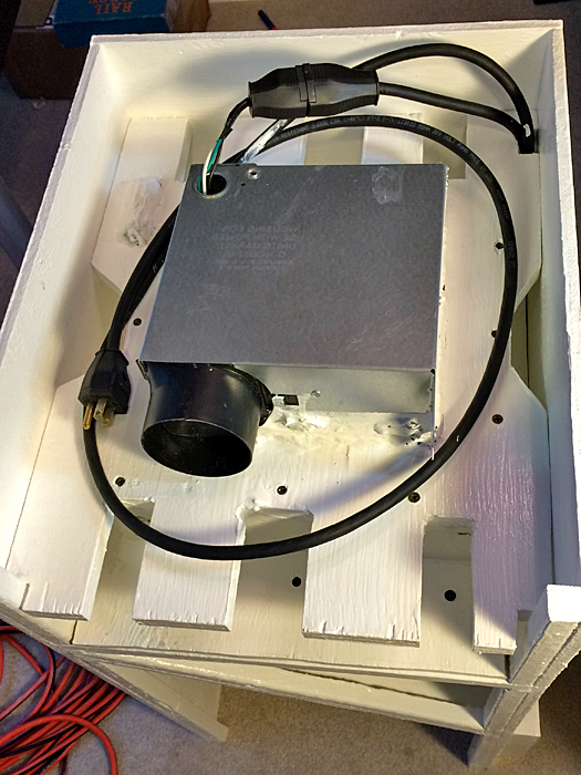
Chris Construction Complete!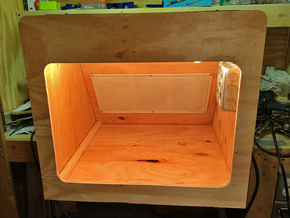 August 19, 2015 Air Brush Paint Booth Update: Construction Completed! Joe advised that the paint booth was completed to my specifications and ready for inspection and pick-up. Since the last visit on 8-17-15, all of the wiring had been completed and the front face was built and installed. The front face was designed to extend downward and upward from the top and bottom of the painting chamber by two inches. The overhang on the sides would be one inch from the left wall and one inch from the right wall. In addition the front face was extended upward over the painting chamber to cover the box housing the light fixtures and wiring. This would provide a smooth, seamless appearance to the front of the paint booth. 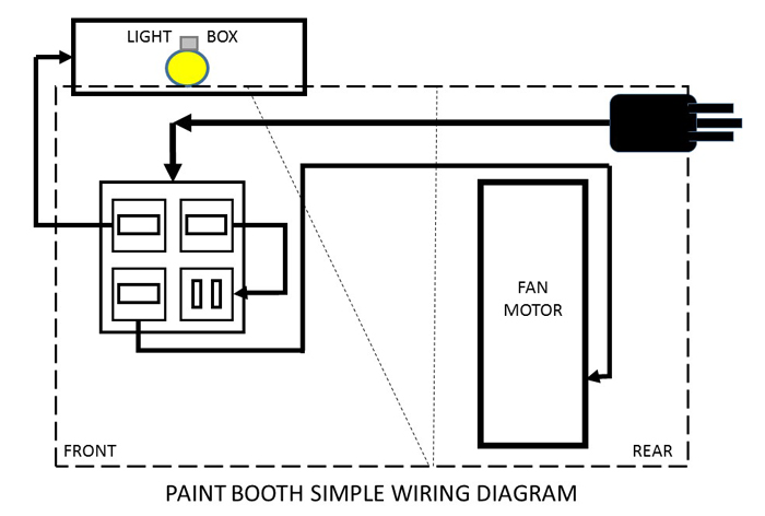 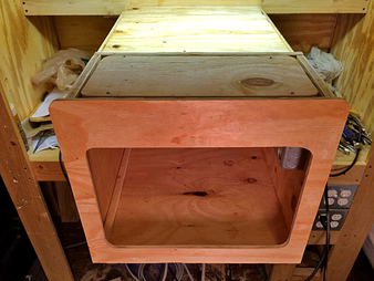 The above simple diagram outlines the basic wiring of the paint booth. A three-prong male outlet extends from the rear of the paint booth. This can plug into any wall outlet to power the paint booth. From here the electricity flows through a cable along the inside of the paint booth to a square steel electrical box mounted inside the painting chamber on the right wall (as viewed from the front). This box houses three switches and one outlet. One switch is the on/off for the lights. The second switch is the on/off for the fan motor. And the third switch is the on/off for the female outlet directly under it. This outlet could be used to power an additional light source or other power tool needed for painting. I plan to draw a more detailed electrical diagram to publish in a future update on this project. As with all electrical projects, do not perform tasks that you are not trained or otherwise qualified to do! 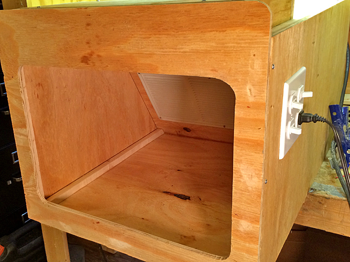 Now the paint booth is in my garage where I have completely disassembled it for priming and painting. All of the exposed wood surfaces will be painted white. This will be the subject of the next update!
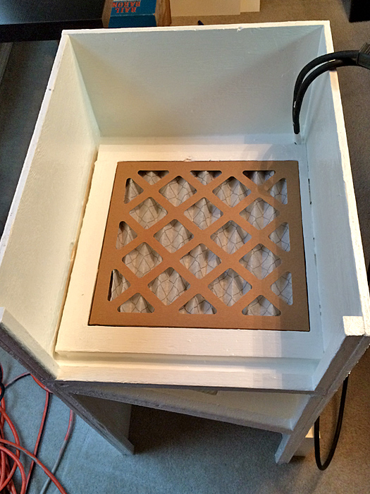
Chris Light Housing Installed - 8-17-2015The below images show the paint booth progress as of 8-17-2015. The light housing has been installed with holes cut into the painting chamber to allow the bulbs to light up the objects being panted. 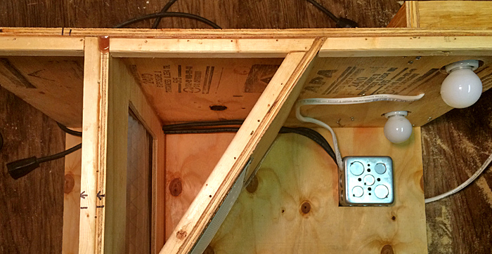 The images in the slideshow below show some of the lighting effects and the wiring involved. Next we will take a look from the rear to see how the wiring and how the modules come out to access the filter. A notch was cut in the upper corner of the modules to allow them to slide out without interfering with the wires. The two main wires running the length of the paint booth from the rear are the electrical cord which attaches to an outside power supply and the power wire coming from the junction box in the front of the paint booth to the fan. Both male and female three-prong plugs are located just outside the fan housing so that the fan can be unplugged from the paint booth allowing the module to slide out of the back. Also of note in the below images is that the manufactured holes in the metal fan housing have been sealed off with silicone. Chris
New Equipment Received - Athearn Cotton Belt SD45T-2 9383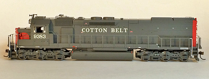 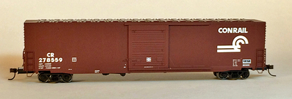 Meridian Speedway management acted on low-inventory numbers of the recently-released Athearn Ready-to-Run Cotton Belt SD45T-2 locomotives an placed a purchase order for one unit. This locomotive, numbered SSW 9383, arrived today! As expected, this locomotive is a wonderful model with enough road-specific details to make it "feel" like and EsPee engine. This is actually the first SP/SSW locomotive I have purchased. Several more will need to be added to the fleet as several consists will be required to operate the SP/NS bridge traffic scheduled to operate across the Meridian Speedway on a daily basis. One other piece of equipment was included with this equipment order. Very reasonably priced Conrail ACF 60' single door auto parts box car CR 278559. This is one of the latest release of 60' auto parts box cars by Atlas. A number of these cars from earlier releases are already rostered in the Meridian Speedway fleet. Chris DM&E Trip - Lincoln, NE to Rapid City, SD...Via Denver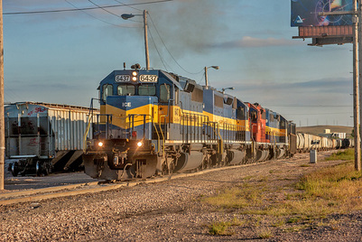 My current assignment as BNSF Valley Dispatcher brought to mind a trip I made nearly two years ago while I was stationed as Terminal Manager in Lincoln, Nebraska. Knowing that changes were ahead for the west-end of Canadian Pacific's former DM&E (Dakota, Minnesota, & Eastern) trackage, myself and friend Nick Huth decided to make a trip to South Dakota to photograph this railroad. The trek to the DM&E would cross paths with several BNSF lines on the Powder River Division which I now dispatch. Nick would be traveling from New Orleans so we decided to rendezvous in Denver, Colorado for this Journey. I would be taking advantage of a three-day weekend by boarding Amtrak train No. 5, the Westbound California Zephyr, in Lincoln just before midnight on the night of Sunday, September 15, 2013. I rode on the head-end with engineers Derek Lewsader and Brian Gordon from Lincoln to McCook. It was a great ride! The railroad community really is a small family. Six years earlier, while working as BNSF Manager of Passenger Operations I made a trip on Amtrak No. 5 from Chicago to Denver. Under the watchful eye of engineer Ben Barnes, the Young Derek Lewsader was student engineer on that particular trip which arrived in Denver on October 17, 2007. One of my favorite in-cab photos that I have taken was the below image of Derek reaching for the radio to talk to the Train Dispatcher at Commerce City outside Denver: 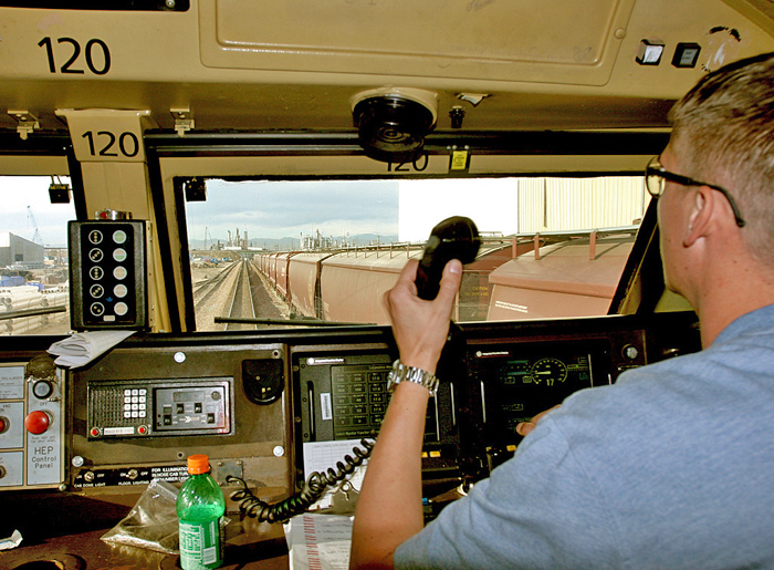 Back to this trip, at McCook, Nebraska I went back to the train where I was able to sleep in an available room in the crew dormitory car. Rest would be necessary for it was a long day and arrival at Denver would be soon! The Amtrak California Zephyr normally operates between Chicago, Illinois and Emeryville, California (Oakland), however today everyone would be de-training at Denver. Colorado had been particularly hard-hit with heavy rainfall and several washouts had the Union Pacific Moffat Line closed west of Denver. The BNSF Front Range Subdivision was also washed out. Continuing passengers would be "bus-bridged" across the affected section of the Rockies and put on another set of Amtrak equipment out of California that was turned around. Downtown Denver was "under-renovation" which meant that we would not be using the famous Denver Union Station. The train terminated at a temporary station facility several blocks away, adjacent to Coors Field. Passenger not transferring to one of the waiting busses had to cross Delgany Street to access the temporary waiting room and station facilities. It was not the grandest entrance into Denver. Train No. 5 arrived in Denver a little before Nick's flight from New Orleans so I had about an hour to kill. Luggage in tow, I headed up the street where there was an elevated intersection with 23rd Street. From here I was able to get a few shots of our train in the temporary depot. A fuel truck was on-hand to fuel the locomotives as well. Temporary Amtrak Depot - Denver, ColoradoStill having a few minutes on my hands, I continued on the overpass to photograph some of the activity around the BNSF Denver diesel facility and yard. I am very fortunate to have made trips to Denver several times as a child and later before the BNSF merger. Denver was almost a magical place then, with the iconic Denver and Rio Grande Western Railroad calling attention to the spectacular Rocky Mountains just to the west and the Burlington Northern parading an impressive sea of Cascade Green locomotives through the Mile High City. These memories made standing here this morning feel very odd. I had been here before, but nothing seemed the same. BNSF Diesel Facility - Denver, Colorado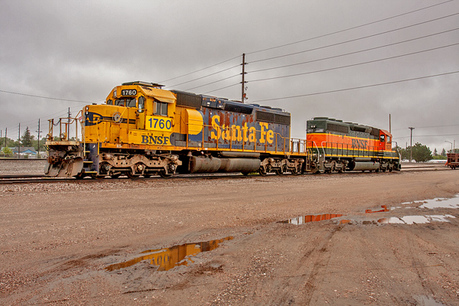 A call from Nick advised he would be at the Amtrak depot with the rental car in a few minutes. I headed back down the bridge to begin the next leg of the journey. Our destination for this day would be Rapid City, South Dakota. The morning was overcast in Denver and the sky continued to darken as we drove northward toward Cheyenne, Wyoming. We could see some remnants of the recent flooding from the Interstate. Both Nick and I have made several trips to Cheyenne in the past. Those trips were centered around railfanning the Union Pacific's busy main line. On this particular day we decided to bypass most of the normal attractions both because of the weather and because of the distance we had to travel. We did make a quick visit to the BNSF yard in Cheyenne where I was able to meet the new Trainmaster. Outside was a pair of SD40-2s idling between assignments. One of which, BNSF 1760, was still wearing its Santa Fe colors; though not as proudly as it once did. North of Cheyenne we left I-25 and headed towards Torrington on Highway 85. Torrington is on the BNSF Valley Subdivision which is the gateway to Guernsey, WY and the bottom end of the famous Orin Line in the Powder River Basin. Little did I know at the time that I would soon be dispatching this territory...again! BNSF does not place a high priority on dispatcher road trips so they are few and far-between. Currently I own the first shift Valley desk which is my motivation for referencing the photos I took on this trip and penning this essay. Our route, Highway 85, made a northwest turn at Torrington where it begins to parallel the BNSF Valley Subdivision towards Lingle, WY. The railroad is single track with a passing siding between Torrington and Lingle named "Texas". The next siding going westward is named "Grattan" and is closer to Fort Laramie. BNSF Valley Subdivision - Lingle, WyomingWe spent about an hour on the Valley Subdivision getting the shot. A light power move pulled into the siding at Texas to meet three eastbound trains. First up was an extra Guernsey, WY to Kansas City, KS manifest symbol H-GUEKCK4-16 led by C44-9W 4006. We set up by the small grain elevator in Lingle to get the shot. Next up was a loaded North Antelope Mine to Rush Tower, MO coal train C-NAMRTR1-38 led by ES44AC 6346. We chose a spot near Milepost 77 to shoot this train because there was a tree!
The final eastbound train was Antlope Mine to Iatan, MO (Sadler) coal train C-ATMSAI0-31 sporting plenty of power. Two Grinstein Green SD70MACs and a pair or ES44ACs led the train while a lone ES44AC was pushing on the rear. The first photo location was between the switches at Grattan. We paced this train for a bit and then shot it a second time at Milepost 74. Before departing Lingle for good we managed to get a going-away shot of the light power finally underway towards Guernsey. Air Brush Paint Booth Progress ReportWork has progressed quickly on the Air Brush Paint Booth Project! I have been busy and am a bit behind, but I wish to post sequential progress reports for project documentation. This report updates status as of 08-13-2015. 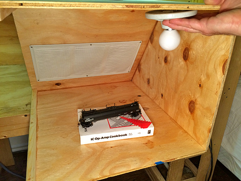 Last Thursday I stopped by my Uncle Joe's apartment to discuss the next steps in the construction of the air brush paint booth and review the progress. Since the previous update, 3/4" x 3/4" wood dowel had been lined around the plywood edges that will connect to the one side panel that will be screwed into place. This was necessary as the plywood itself was too thin to screw into directly. The top, bottom, and other side had been glued together. This last side was cut into two panels, allowing separate removal to access different components separately. 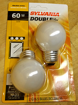 I had also purchased a couple of 60 watt light bulbs which I brought over to test fit. They will screw into two very basic porcelain light fixtures that will be mounted to the ceiling of the paint booth. We discussed the depth of the bulbs in the booth and decided to build a structure above the roof to house the wiring and porcelain fixtures. This would require holes to be cut in the current ceiling to allow the bulbs to rest within the painting chamber. We also discussed the front piece which will act as a visual shield for the lighting. At this point it seemed that this shield would have to come down about 3 1/2 inches to block the bulbs from view. This factored into the decision to raise the light housing above the ceiling. The final dimensions of the front portal will be one of the last decisions made. One other minor detail worth mentioning is that all of the manufactured holes in the metal fan housing were sealed shut with silicone. All possible "leaks" will be sealed to ensure that all of the air processed through the filter will come from the painting chamber. 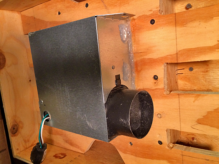 Chris
Five New Gondolas Arrive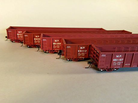 The Meridian Speedway took delivery of five new gondolas today! These cars are ExactRail's special of the month with pricing about $10.00 off each car. I had already purchased two of the beautiful Missouri Pacific cars, MP 651061 and MP 651374. Both wore MP markings with the UPRR shield logo. These cars are of particular interest to me as when I was an Assistant Trainmaster for the BNSF in Fresno, California we would get cuts of about 20 of these cars delivered by the Union Pacific for us to spot to several local scrap customers. Specifically, Levi's Iron and Metal Company and Bruno's Iron and Metal. I would usually make a recon run before the third shift yard jobs came on duty to verify the list of the interchange cars. Handing an accurate list to the switch crews from the beginning could avoid significant delay! There will be a scrap dealer on my Vicksburg Terminal layout that will be supplied primarily with these cars. Today's delivery brings the fleet of MP gondolas up to seven. The new arrivals include three more cars with the UPRR shield logo: MP 651187, MP 651216, and MP 651255. In addition, two pre-merger cars wearing the Missouri Pacific eagle logo were delivered: MP 650911 and MP 651112. These care are simply stunning! Chris
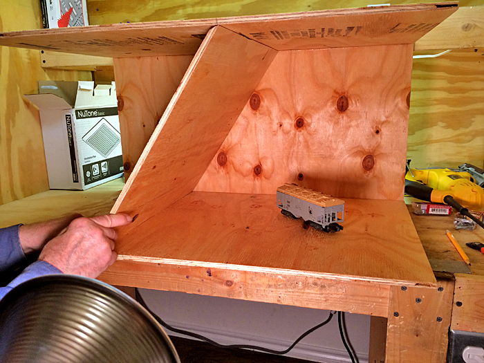
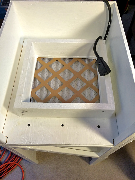
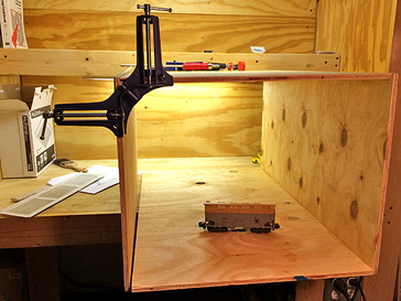
Filter and Fan Modules CompletedWork is progressing nicely on the air brush paint booth. My uncle, Joe Scorsone, has been a big help with this project! The center wall that forms the angled back of the painting chamber has been installed with the ventilation grill cut in. 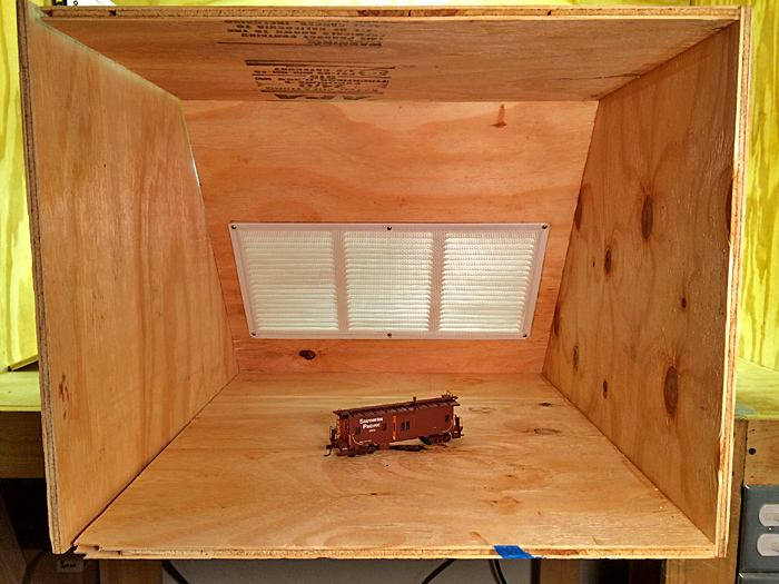 The next component is a vertical wall that that houses the air filter. This structure will be mounted permanently behind the paint chamber. It will be sealed around the perimeter forcing all air to flow through the filter. A reduction chamber module is the next component. This chamber will slide into the rear of the paint booth and will screw into the wall with the filter. This keeps airflow coming out of the filter in a space the same dimensions of the filter as opposed to the dimensions of the paint booth. 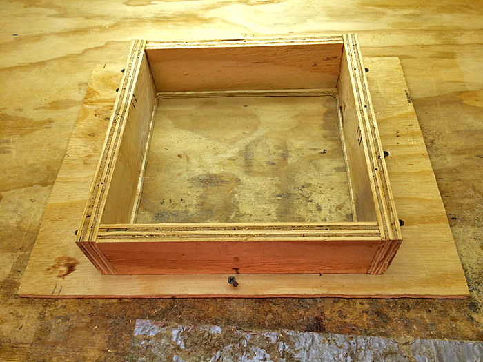 The final module houses the exhaust fan itself. This component fits snugly against the reduction chamber so that all air passing through the filter will be pulled into the fan. Like the reduction chamber module this component slides into the rear of the paint booth and screws in place to the reduction chamber module. All holes in the module and the fan housing will be sealed to ensure that all airflow travels from the reduction chamber to the exhaust. Large notches will be cut into the fan housing module allowing the reduction chamber module to be easily unscrewed from the rear of the paint booth to allow for changing of the air filter. Next these three structures were assembled together and inserted into the paint booth for a test fit. 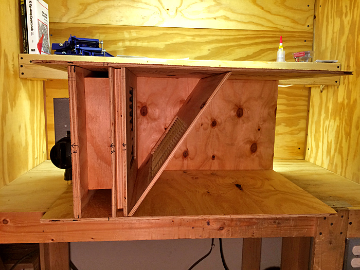 They all came together nicely! The paint booth was positioned by n outlet for a test run. With the filter wall not sealed and the fourth wall of the filter held loosely to the rest of the structure the air flow into the vent at the back of the painting chamber was sufficient enough to hold the three full-sized stapled papers with the earlier paint booth drawings firmly to the grill! There is no doubt now that once the paint booth is painted and sealed there will be sufficient airflow provided by this fan to provide the intended ventilation! Below for reference is an image of the bottle of glue used to attache the permanent pieces. Tightbond III Ultimate Wood Glue is very strong and will not dissolve once set. So far I have been very impressed with its properties. 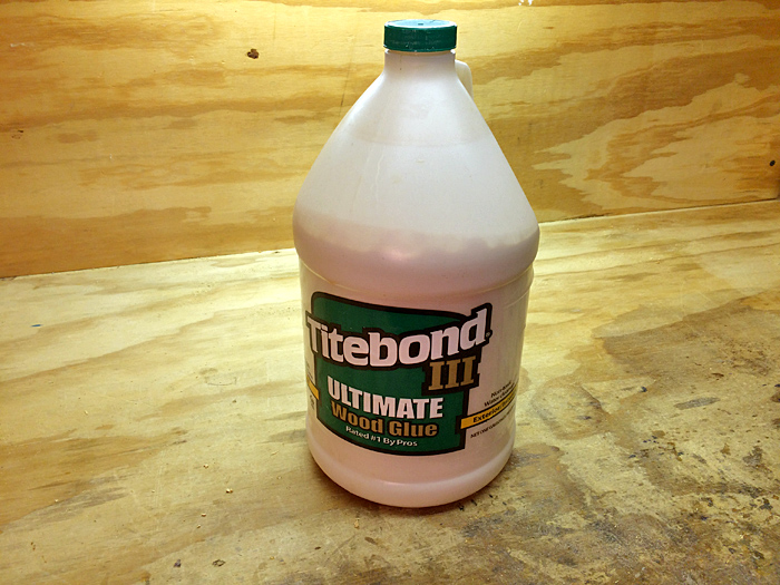 Next will be firming up of these components and the overall structure and then some electrical work!
Chris Air Brush Paint Booth Takes Shape!
 The original design I sketched had the fan housing sitting on top of the ventilation chambers as an external feature. With the box fabrication in progress and the components purchased and on-hand, experimentation with positioning was possible. Joe suggested that there is enough room in the ventilation chamber for the fan housing to be enclosed with the main body for the paint booth. Not a bad idea! There are several possible configurations which would require the location of the filter access door to be relocated. At this point, not a big deal. The below slideshow displays various component configuration possibilities: Feedback from a number of you has indicated concerns about the fan motor being an ignition source for flammable paint vapor.... As it turns out this motor does have exposed brushes! 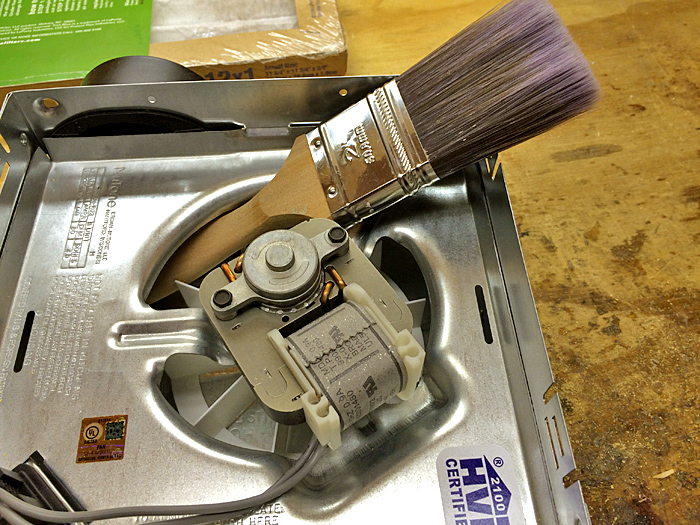 JUST KIDDING!!!! Ha ha ha....
Actually the fan motor (NuTone Model 696N) is an enclosed shaded pole, thermally protected, 120vAC, 60 Hz, .9 amp. design. I believe that given the travel distance the paint vapors will travel from the airbrush to the fan, via a filter, the potential for ignition with this fan motor is minimal. The real test will come when the motor's power is tested in the enclosed chamber to see if it is strong enough to maintain proper airflow out of the painting chamber. My initial calculations indicate that it will work. Chris A Trip to Home Depot for the Paint Booth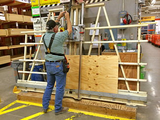 I have enlisted the assistance of my uncle, Joe Scorsone, for the airbrush paint booth project. We are going to stick closely to the original design, discussed earlier. One change will be to have the filter accessed through a door in the rear instead of through the internal panel with the louvers. This will allow that piece to be fixed in place. Yesterday we made a trip to the Roanoke Home Depot to acquire more supplies, including a 4x8 sheet of plywood cut to three 18"x30" strips, two 15"x30" strips, and one 15"x18" panel for the rear. There is enough material left over to fabricate the filter groove and supply shelves in the front. In addition lighting, wire, switches, and hinges were among the list of supplies. Many thanks to my uncle for accepting this challenge! Chris
|
Categories
All
Author:
|
 RSS Feed


Proudly powered by Weebly
- - - Homepage of the Natchez Trace and Orient Railway and Texas and Great Northern Railway - HO Scale Meridian Speedway - Created by Christopher M. Palmieri - - -
© Christopher M. Palmieri - 1st Publish 12-10-2014
© Christopher M. Palmieri - 1st Publish 12-10-2014