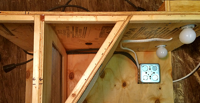
Light Housing Installed - 8-17-2015The below images show the paint booth progress as of 8-17-2015. The light housing has been installed with holes cut into the painting chamber to allow the bulbs to light up the objects being panted. The images in the slideshow below show some of the lighting effects and the wiring involved. Next we will take a look from the rear to see how the wiring and how the modules come out to access the filter. A notch was cut in the upper corner of the modules to allow them to slide out without interfering with the wires. The two main wires running the length of the paint booth from the rear are the electrical cord which attaches to an outside power supply and the power wire coming from the junction box in the front of the paint booth to the fan. Both male and female three-prong plugs are located just outside the fan housing so that the fan can be unplugged from the paint booth allowing the module to slide out of the back. Also of note in the below images is that the manufactured holes in the metal fan housing have been sealed off with silicone. Chris
2 Comments
Bill Trbovich
8/21/2015 02:30:12 am
Chris,
Reply
8/21/2015 03:30:57 am
Bill, Thanks for the note. You have an advantage with building a new structure in that you can incorporate a vent in the wall or ceiling to connect your paint booth to.
Reply
Your comment will be posted after it is approved.
Leave a Reply. |
Categories
All
Author:
|
Proudly powered by Weebly
- - - Homepage of the Natchez Trace and Orient Railway and Texas and Great Northern Railway - HO Scale Meridian Speedway - Created by Christopher M. Palmieri - - -
© Christopher M. Palmieri - 1st Publish 12-10-2014
© Christopher M. Palmieri - 1st Publish 12-10-2014

 RSS Feed


