Air Tank Upgrade, Compressor Failure, and First PaintLast Friday, yes...Friday the 13th, was a busy day for Meridian Speedway Paint Shop progress! The morning began with a trip to Home Depot for a few components to upgrade my air tank, followed by the disappointment of the failure of my compressor to start up. That evening Joe Bohannon of the Chinook Lines and his wife came over for dinner. He quickly found the issue with my compressor and fixed it. He also brought a few locomotive shells, his own paint experiment, and his airbrush. All of this led to an impromptu test-run of the new paint booth!  The air intake valve that I have used on my air tank will work with any hose fitting that will air-up a car tire. I have had this tank for over 20 years and it was designed to take to the corner gas station and fill with air. Moving forward, I never have made adjustments to the original plumbing (built by Lenny DiMartino), not even after I purchased a large air compressor over 15 years ago. This meant that as the tank ran out of air I had to stop the painting process and manually refill the air tank. Considering the time invested in this paint booth project to the end of a better painting process and higher quality painted models, I decided now was the time to fix this. I was hopeful that there would be quick-connect appliances that would fit right onto the current threaded intake pipe, however, I was not to be so lucky! Instead I decided that the best route would be to install a quick connect valve between the tank and the existing piping, allowing two methods for filling the tank with air. The below slideshow hi-lights the modifications to the air tank.  Modification complete, I was now ready to break-in the paint booth with a test run...or so I thought! I had the window exhaust panel in place and connected to the paint booth. The air tank hooked up to my airbrush via a new hose (the old one desperately needed to be replaced), and I had hooked up the compressor to the air tank. I was excited by this arrangement as the compressor hose is long enough to allow the very noisy compressor to remain in the garage while connecting to the air tank several rooms away. Then I plugged in the compressor, flipped the power switch, and...nothing! My trusty compressor of many, many years decided to pick this moment to not start! I was displeased. To YouTube I went to research this issue and figured it was probably the starter switch. 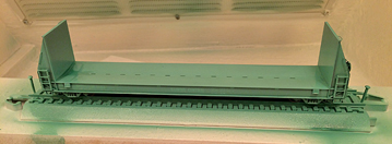 Coincidentally fellow DFW area model railroader Joe Bohannon had reached out to me on this day to see if there were any opportunities to do any model railroading. I explained to him my task for the day and my obstacles. By the end of the conversation a plan was in place and we had company lined up for dinner. Joe and San Antonio area modeler Anthony Lorch had already collaborated on the issue of the disappearing brands of paint facing the hobby and are experimenting with a creative solution. Joe has some unique colors for the locomotives of his Proto-Freelanced "Chinook Lines". Most notably is a difficult to describe gray/blue/green...ish color that he got from a German military color pallet. He thought I might be interested in this as the greens for my T&GN and NT&O locomotives were victims of Testors' genocide of the Floquil line of paint and are no longer available. Joe, with a clear head, quickly honed in on the issue with my compressor, a power wire had come off the connection under the starter switch cover. The fix was very simple...and we had air! Joe did bring his own compressor and airbrush along with a quart of acrylic enamel paint from Sherwin Williams to test. The quart, matched to his model paint using Sherwin Williams' "Spectrometer", cost $22. The quart of course yields 32 ounces. Considering that most model paints are sold in the range of $3 to $6 per ounce, the cost savings is worthy of notice. After dinner, it was time to paint. I decided that the Chinook Lines color would make a good primer so I grabbed a Walthers 50' Seico Pulpwood Flatcar from my repaint stock, removed the couplers, installed shop trucks, and we were set. Unfortunately I guess I failed to properly clean my airbrush after the last use and an unexpected blast of air went into the paint bottle, instantly adding a neat gray/blue/green...ish explosion pattern to the inside of the paint booth. It was christened properly! Deciding to deal with that later, we substituted Joe's double-action paint brush and we were spraying. A few test sprays were in order and the paint/water mixture was adjusted. The below slide show shows the the painting of the pulpwood car as well as one of Joe's GP7 shells. So I was definitely out of my comfort zone here. I have never before sprayed with a double-action airbrush, never before airbrushed a water-based paint, and of course the painting environment was new. The paint booth worked like a charm! No explosions, no fire, and excellent ventilation. The ultimate test came from Joe's wife who declared that she could not smell paint in the house.
I must admit I was a bit skeptical about using house paint on a model. The result of this test has my attention! The finish was remarkably smooth and thin. I think that once I get comfortable with the properties of this paint there are excellent results to be had. Many thanks to Joe Bohannon for his assistance! Now to get this airbrush cleaned out... Chris
0 Comments
Paint Booth Ready For ServiceIt has been a while since my last update on the paint booth. My children's football, cheer, and gymnastics schedules have cut into my available blog time considerably. I am pleased to announce that all components are complete, tested, and ready for service! Going into off days here, I intend to get a few items painted. 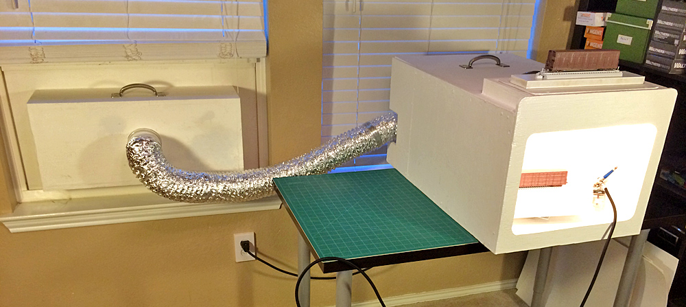 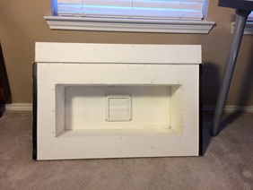 The last booth update included the initial plans for the window exhaust panel. There are only two major design changes to this panel. First, the plan called for an enclosed chamber with a connection to the paint booth duct on the interior panel and a louvered vent on the exterior panel. The exterior panel design was changed, with the center being left open for the entire width and height of the chamber. This was done to allow for better ventilation and dilution of the contaminated air. Another design change was to the top of the panel. Instead of having the top a single panel that tucked behind the window, a channel was created that would cradle the bottom of the lowered window, creating a more secure and air-tight fit. A late modification to both the paint booth and the window exhaust panel was the addition of stainless steel handles to assist with movement of the items as their size makes them a bit cumbersome. The below slideshow hi-lights the window exhaust panel and its placement in the window opening: Once installed in the window, a 4-inch dryer duct with specially designed PVC sockets fits snugly on both the fan motor exhaust and the back of the window exhaust panel. There were some holes in the metal casing of the fan which I sealed with silicone. The next series of images show what the window exhaust panel looks like from the outside. You can notice the change in position of the center louvers when the paint booth fan is turned on. I also created a few accessories to assist with painting. I made a turntable using a couple of scrap pieces of MDF as well as a ball-bearing turntable bracket which cost about $5.00 at the Home Depot. This works remarkably well and was quite simple to make. In addition I nailed two pieces of snap-track to two separate scrap MDF strips for models to sit on during the painting process. These track panels will allow the painted models to be removed from the paint booth without having to be touched. In order to help secure the models during the painting process I used crazy glue to lock one axle on each of the four "shop-trucks" that I put under the models. This is essentially like securing the equipment with a hand brake as I do not want free-rolling equipment on the turntable during painting. A late modification to the paint booth was the addition of a brass hook to each of the side walls inside the main painting chamber. These were stretched open with pliers to allow the paintbrush to fit. This now provides a secure place to rest the airbrush with bottle attached during the painting process. The below slideshow hi-lights this mod as well as the operation of the turntable in the paint booth: It seems like this project has taken an eternity to complete! Many thanks to my uncle Joe Scorsone who did most of the actual construction work on both the paint booth as well as the window exhaust panel. Looking through my blog posts, however, reveals that the timeline for this project only lasted four months! The first blog post was published on 7-9-2015.
I hope to be able to share many great projects that will come form this paint booth! Chris Window Exhaust Box Concept on Paper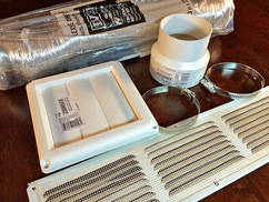 The Airbrush Paint Booth is designed to capture all of the air contaminated by harmful vapors during the painting process and keep them out of the indoor breathable air supply. The design of the Paint Booth itself has to be functional and efficient. Once captured by the ventilation process, there must be a seamless flow to export the contaminated air to the outside. This is where the Paint Booth Window Exhaust Box comes in. The fan exhaust is a 3-inch diameter pipe which can easily connect to 3-inch foil dryer duct. While this duct could be run to the outside through an open door or window, that would leave an opening that would allow outside air (even the exported contaminated air) to flow freely into the indoor environment where painting is taking place. 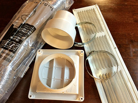 I decided that the logical exit port should be a window as it could be closed tightly around an exhaust panel that was sized properly. Off to Home Depot I went to examine available components and formulate the design. There is enough wood left over from the 4'x8' piece of plywood used to construct the paint booth itself, so additional wood was not needed. I also had on-hand a 16-inch by 4-inch vent panel that I had purchased earlier for the paint booth but ended up not using. This also will fit into the Exhaust Box design. Additional materials purchased for the exhaust box were: 1) One 3-inch x 25-foot flexible aluminum foil duct 2) One 3-inch to 4-inch diameter duct increaser 3) One 4-inch diameter louvered exhaust hood (6" x 6") 4) Two 3-inch adjustable metal worm gear clamps 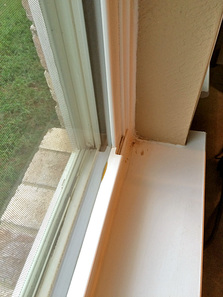 Next I picked a window and took some measurements. It is important to note that the dimensional specifications in the below design are specific to fit the window frame opening that I will be using. If you will be building a window exhaust box, you will need to adjust as appropriate to fit your window design and opening. The width of the main window opening is 32 inches. This 32 inch width which fits snugly under the raised window and fits flush against a slightly narrower external opening. This will make it very easy to seal off the outside air from the room interior. Looking at the hardware components and sill/frame outline, I decided that a height of 12 inches would be appropriate for the design of the Window Exhaust Box. Rather than free-handing the design drawing like I did for the Paint Booth, I decided to use PowerPoint for the below drawings. These drawings are NOT to scale! Hopefully they are easy to understand: Drawing 1 - Exterior Window Panel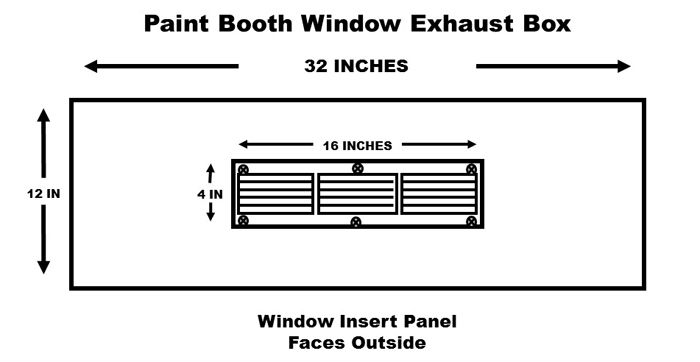 The exterior window panel is the largest component. This is the exterior wood face of the Exhaust Box that fits snugly into the window opening. This window opens by lifting the bottom window upward. The bottom and two sides will be surrounded by the window frame. Once in place, the window can be lowered until it contacts the top of this panel, completing the seal between the outside and the inside. The 16-inch by 4-inch vent cover is the only piece of hardware that will be attached to this panel. This vent will be cut directly in the center of the panel. Drawing 2 - Interior Room Panel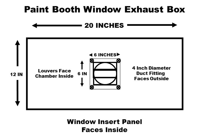 Opposing the Exterior Window Panel is the Interior Room Panel. This panel does not need to be as wide as the window panel, but it does need to be wide enough for a connecting chamber to be built between the two panels containing airflow between the two. Therefore the 16-inch wide exterior vent cover and the 6-inch square louver cover will have to be within the dimensions of the inner chamber. I decided that a width of 20 inches and a matching height of 12 inches would be sufficient Drawing 3 - Exhaust Box Top View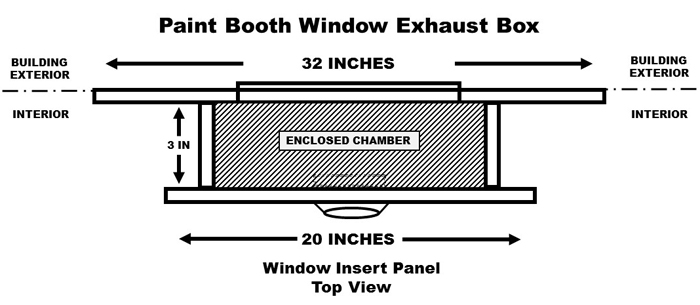 The top view shows how the panels will come together. Airflow from the 3-inch diameter flexible foil duct will enter the chamber via the 3-inch to 4-inch adapter that connects to the 4-inch diameter port of the inward-facing louvered exhaust hood. The louvers open easily in the direction of air-flow and shut when the fan is off keeping small critters outside and sealing off any reverse air flow. From here the air enters a small chamber that forces the air to exit the window through the 16-inch by 4-inch vent in the exterior window panel. Drawing 4 - Exhaust Box Side View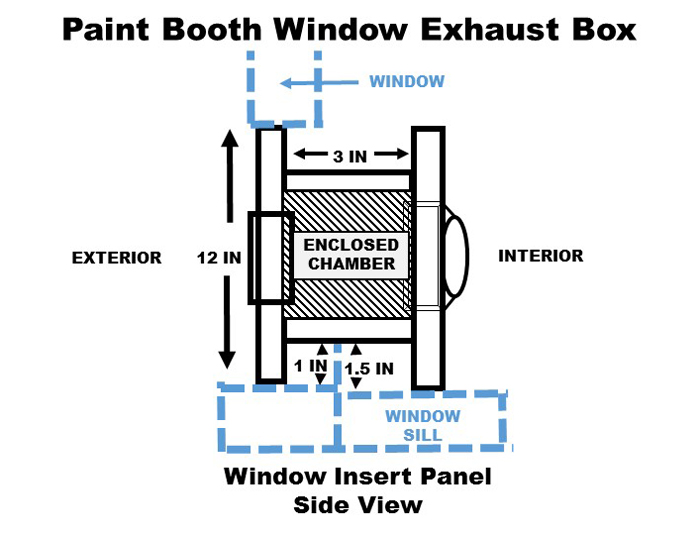 The side view reinforces the top view. Measurement of the window revealed that the top of the window sill is actually 1/2-inch lower than the top of the window opening on which the Exterior Window Panel will rest. There is also a 1-inch lip extending upward from the window sill that seals off the bottom edge of the window when it is fully lowered. Therefore, the bottom of the enclosed chamber connecting the interior and exterior panels much be high enough to clear this lip. The interior panel will also be placed 1/2-inch lower than the exterior panel to compensate for the lower sill. This will make sure that the exterior panel is "At Rest" in the snug position in the window opening. For the purpose of these drawings I have indicated a depth of three inches for the connecting chamber between the two panels. The sill dimensions will allow a total depth of seven inches. As I review the proximity of the Louvered Exhaust Hood to the external vent I ma consider some additional depth - perhaps five inches to reduce the velocity of deflected air off the inside of the external window panel. Chris
First Y&MV Freight Car Decals Ready To Go To PressThe Y&MV has outsourced the development of the decals for its fleet of Thrall Door Boxcars to the Design Team at Stephens Railcar of Dadeville, Alabama. While the actual placement of some of the items may be adjusted on these cars, all of the components are in place! 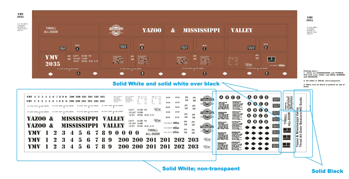  Many thanks to Hank Stephens for his assistance with this project. This particular decal set was particularly labor intensive with much small writing, including the door opening and closing instructions. Working through the revisions was a pleasure. Hank made the process very user friendly. I specifically requested that he include a "Stephens Railcar" shop logo as I would like to simulate some cars painted by an off-line shop. Inspiration for the concept came from the logos for Zwolle Railcar that I recall seeing stencilled on cars painted by Zwolle Railcar of Zwolle, Louisiana in the 1990's. As soon as I can find a photograph of that logo I intend to have it included in a future decal set. Highball Graphics will print the decal sets. This will be the first time I have worked with this company. They come highly recommended and I am looking forward to the process. Now I need to design and complete the window vent for my spray booth exhaust so that I can get the first two boxcars decal ready! Chris Paint Booth Painted and Assembled
Several cans of primer and house paint left over from previous home projects were used so I did not have to spend any money for paint. First I finished up a can of white primer on all of the components. This took a couple of days to get all of the sides and angles covered. Next, I had a half can of white semi-gloss paint which I applied to all of the components in the same manner. I choose white to intensify the lighting inside the painting chamber and to create a non-biased lighting effect on the objects being painted. The paint was a little old and thick, but worked just fine. I like the heavy utilitarian look. All of the electrical wires and components were sealed with silicone before painting. The thick paint was sufficient enough to cover all of the silicone which has a repellent property to thinner paint. 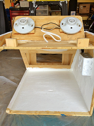 I debated the pros and cons of taking apart the light box and decided to go ahead and disassemble it to paint the inside. The light box sits on top of the front of the painting chamber and serves as an external housing for the porcelain light fixtures for two light bulbs. This takes the wiring and the fixtures out of the painting chamber so that the bulbs are out of the way of the painting process. The porcelain fixtures are mounted upside-down on raised legs on the top panel. It was necessary to put these legs on to allow the wiring access to the fixtures. Of note, the top panel of the light box is cut just a little smaller than the frame it sits in. Also, the two holes in the roof of the painting chamber are cut a little larger than the porcelain light fixtures. The purpose of this is to allow air to flow into the light box from the outside and then into the painting chamber at the base of the light bulbs. When the Paint Booth vent is turned on external air will flow from the inside of the light box into the painting chamber and then into the vent at the back of the paint booth. This current serves two purposes. First it creates a natural cooling airflow around the light bulbs which do generate some heat. Second this flow will carry any lingering vapors in the painting chamber away from the bulbs ensuring that there is not a buildup of flammable vapor around the bulbs. 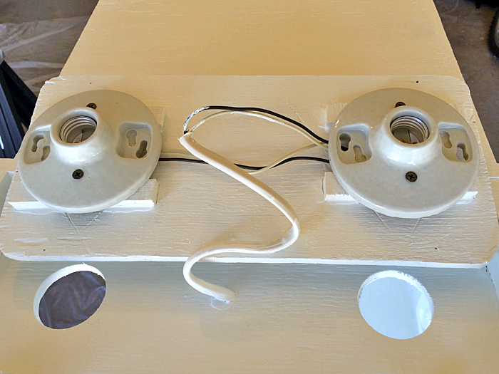 The below slideshow consists of a number of images of the components during this painting process. I did take the time to mask certain things like the switches, outlet, light fixtures and plugs. Four saw horses were placed over a tarp in the garage for painting. Two saw horses supported the main body of the paint booth. Two surplus wooden dowels (thanks to Elfa sales at the Container Store over the years) were placed across the remaining two saw horses to support the other components while being painted. After several days of painting and drying the components were brought inside for reassembly. All of the items fit nicely, though I did need to sand the edges of the reduction chamber as the paint made it to big to seat properly. The first item re-installed was the white air intake grill at the bottom rear of the painting chamber. Six small screws hold this in place. As it came in a white color, this component was not painted. Next the paint booth was stood on-end and the filter, reduction chamber, and fan housing were inserted and screwed in place from the rear.
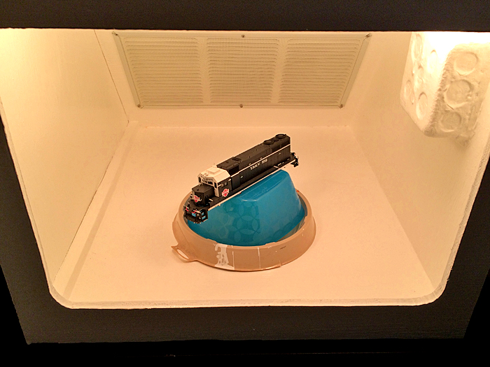
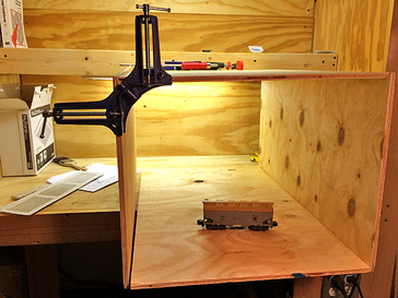
The light switch cover went on next and then the open side panels were screwed into place. The very last thing, of course, was to put in the light bulbs. Plugged in, the lights, fan, and auxiliary switch and socket worked flawlessly. I still have to select, order, and install a turntable for the painting chamber. To test the final effect, I used a paint can drip container and a plastic bowl to simulate the turntable and used the shell of my Y&MV SD35 552 to pose for the below shots: The paint booth project is almost over as just a few things are needed to place it in service. The vent block that will fit into a window frame needs to be constructed and I still need to buy the dryer ducting to connect the fan vent outlet to the window vent block. As painting projects are undertaken and the paint booth gets some use, I am sure mods to make it more user friendly will become evident. Those updates will be posted in this blog labeled with the Paint Booth category.
Chris Construction Complete!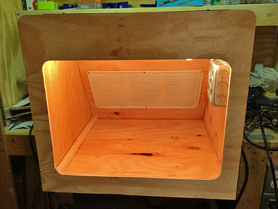 August 19, 2015 Air Brush Paint Booth Update: Construction Completed! Joe advised that the paint booth was completed to my specifications and ready for inspection and pick-up. Since the last visit on 8-17-15, all of the wiring had been completed and the front face was built and installed. The front face was designed to extend downward and upward from the top and bottom of the painting chamber by two inches. The overhang on the sides would be one inch from the left wall and one inch from the right wall. In addition the front face was extended upward over the painting chamber to cover the box housing the light fixtures and wiring. This would provide a smooth, seamless appearance to the front of the paint booth. 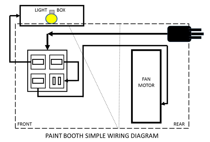 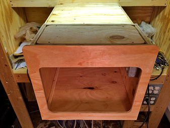 The above simple diagram outlines the basic wiring of the paint booth. A three-prong male outlet extends from the rear of the paint booth. This can plug into any wall outlet to power the paint booth. From here the electricity flows through a cable along the inside of the paint booth to a square steel electrical box mounted inside the painting chamber on the right wall (as viewed from the front). This box houses three switches and one outlet. One switch is the on/off for the lights. The second switch is the on/off for the fan motor. And the third switch is the on/off for the female outlet directly under it. This outlet could be used to power an additional light source or other power tool needed for painting. I plan to draw a more detailed electrical diagram to publish in a future update on this project. As with all electrical projects, do not perform tasks that you are not trained or otherwise qualified to do! 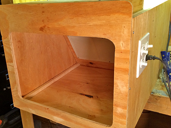 Now the paint booth is in my garage where I have completely disassembled it for priming and painting. All of the exposed wood surfaces will be painted white. This will be the subject of the next update!
Chris Light Housing Installed - 8-17-2015The below images show the paint booth progress as of 8-17-2015. The light housing has been installed with holes cut into the painting chamber to allow the bulbs to light up the objects being panted. 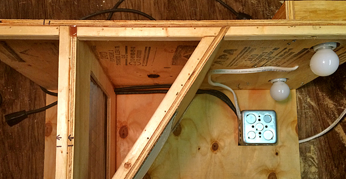 The images in the slideshow below show some of the lighting effects and the wiring involved. Next we will take a look from the rear to see how the wiring and how the modules come out to access the filter. A notch was cut in the upper corner of the modules to allow them to slide out without interfering with the wires. The two main wires running the length of the paint booth from the rear are the electrical cord which attaches to an outside power supply and the power wire coming from the junction box in the front of the paint booth to the fan. Both male and female three-prong plugs are located just outside the fan housing so that the fan can be unplugged from the paint booth allowing the module to slide out of the back. Also of note in the below images is that the manufactured holes in the metal fan housing have been sealed off with silicone. Chris
Air Brush Paint Booth Progress ReportWork has progressed quickly on the Air Brush Paint Booth Project! I have been busy and am a bit behind, but I wish to post sequential progress reports for project documentation. This report updates status as of 08-13-2015. 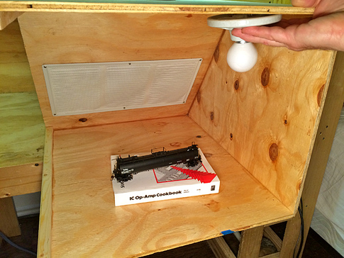 Last Thursday I stopped by my Uncle Joe's apartment to discuss the next steps in the construction of the air brush paint booth and review the progress. Since the previous update, 3/4" x 3/4" wood dowel had been lined around the plywood edges that will connect to the one side panel that will be screwed into place. This was necessary as the plywood itself was too thin to screw into directly. The top, bottom, and other side had been glued together. This last side was cut into two panels, allowing separate removal to access different components separately. 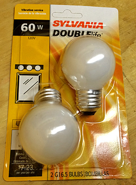 I had also purchased a couple of 60 watt light bulbs which I brought over to test fit. They will screw into two very basic porcelain light fixtures that will be mounted to the ceiling of the paint booth. We discussed the depth of the bulbs in the booth and decided to build a structure above the roof to house the wiring and porcelain fixtures. This would require holes to be cut in the current ceiling to allow the bulbs to rest within the painting chamber. We also discussed the front piece which will act as a visual shield for the lighting. At this point it seemed that this shield would have to come down about 3 1/2 inches to block the bulbs from view. This factored into the decision to raise the light housing above the ceiling. The final dimensions of the front portal will be one of the last decisions made. One other minor detail worth mentioning is that all of the manufactured holes in the metal fan housing were sealed shut with silicone. All possible "leaks" will be sealed to ensure that all of the air processed through the filter will come from the painting chamber. 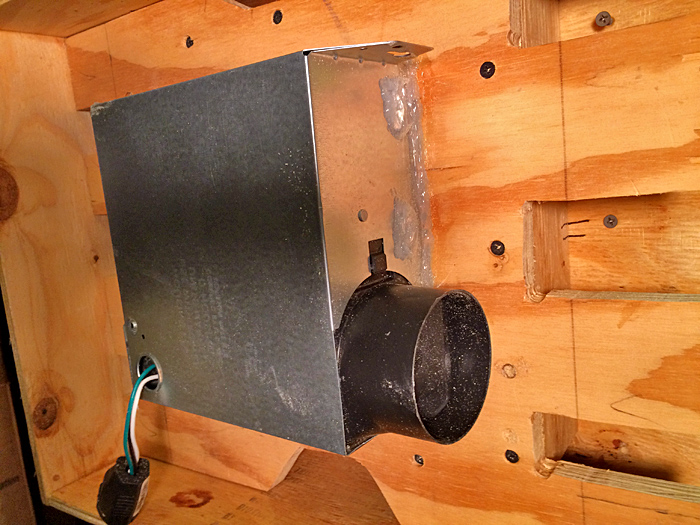 Chris
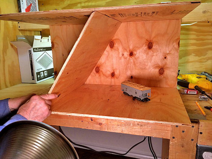
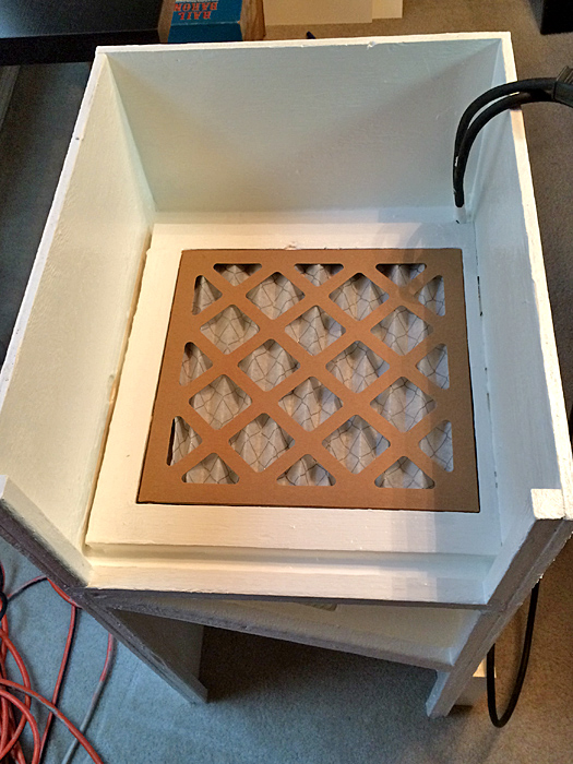
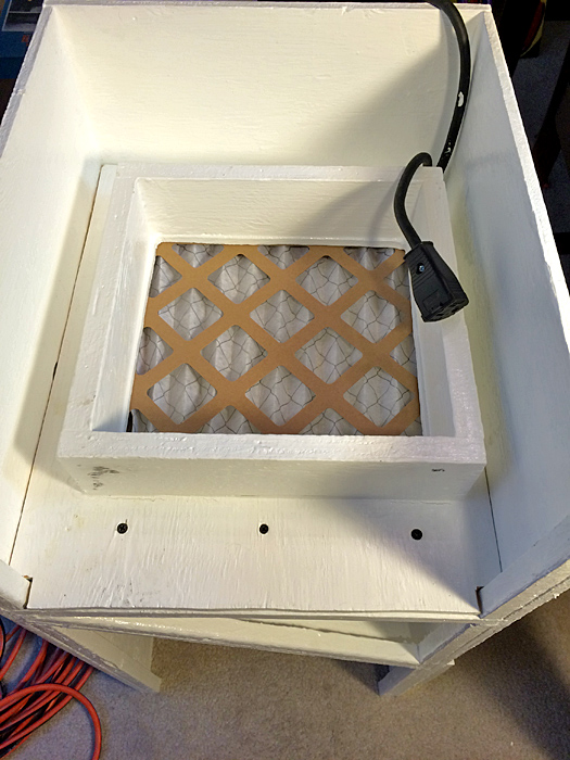
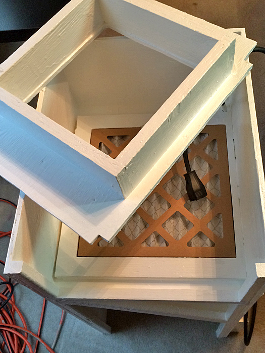
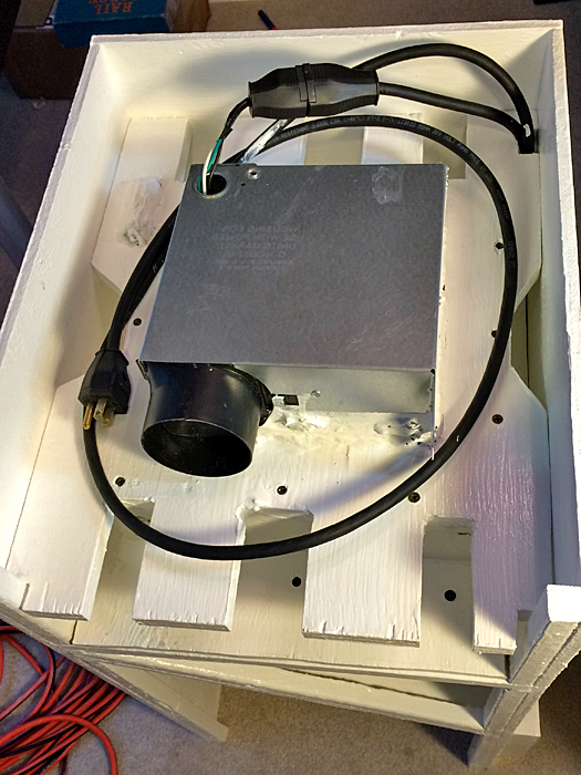
Filter and Fan Modules CompletedWork is progressing nicely on the air brush paint booth. My uncle, Joe Scorsone, has been a big help with this project! The center wall that forms the angled back of the painting chamber has been installed with the ventilation grill cut in. 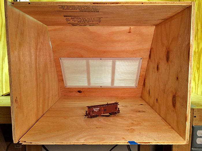 The next component is a vertical wall that that houses the air filter. This structure will be mounted permanently behind the paint chamber. It will be sealed around the perimeter forcing all air to flow through the filter. A reduction chamber module is the next component. This chamber will slide into the rear of the paint booth and will screw into the wall with the filter. This keeps airflow coming out of the filter in a space the same dimensions of the filter as opposed to the dimensions of the paint booth. 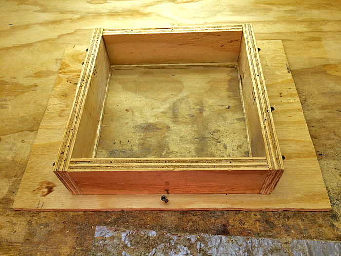 The final module houses the exhaust fan itself. This component fits snugly against the reduction chamber so that all air passing through the filter will be pulled into the fan. Like the reduction chamber module this component slides into the rear of the paint booth and screws in place to the reduction chamber module. All holes in the module and the fan housing will be sealed to ensure that all airflow travels from the reduction chamber to the exhaust. Large notches will be cut into the fan housing module allowing the reduction chamber module to be easily unscrewed from the rear of the paint booth to allow for changing of the air filter. Next these three structures were assembled together and inserted into the paint booth for a test fit. 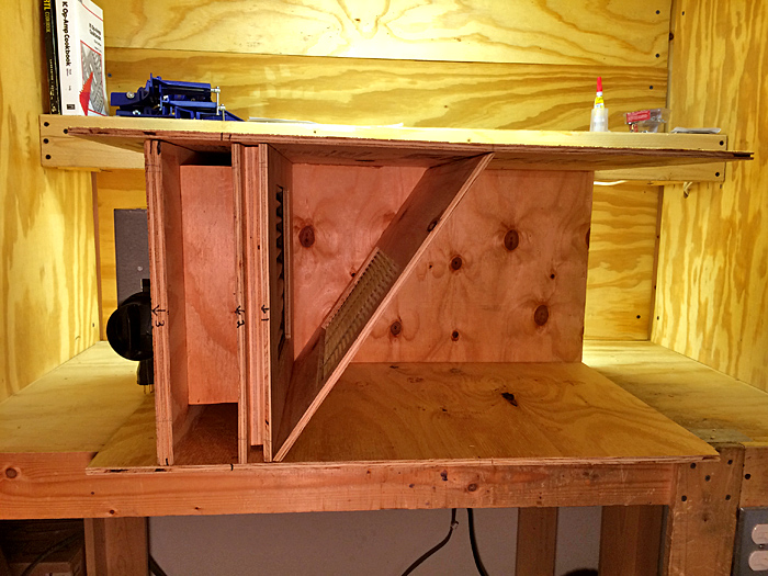 They all came together nicely! The paint booth was positioned by n outlet for a test run. With the filter wall not sealed and the fourth wall of the filter held loosely to the rest of the structure the air flow into the vent at the back of the painting chamber was sufficient enough to hold the three full-sized stapled papers with the earlier paint booth drawings firmly to the grill! There is no doubt now that once the paint booth is painted and sealed there will be sufficient airflow provided by this fan to provide the intended ventilation! Below for reference is an image of the bottle of glue used to attache the permanent pieces. Tightbond III Ultimate Wood Glue is very strong and will not dissolve once set. So far I have been very impressed with its properties. 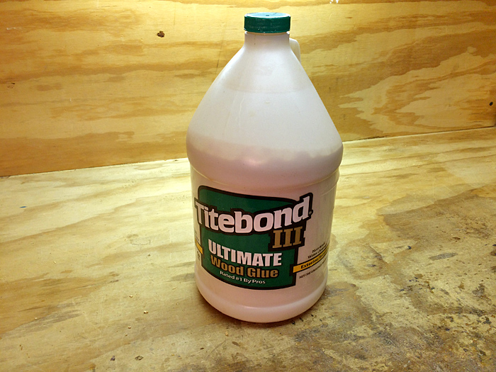 Next will be firming up of these components and the overall structure and then some electrical work!
Chris Air Brush Paint Booth Takes Shape!
 The original design I sketched had the fan housing sitting on top of the ventilation chambers as an external feature. With the box fabrication in progress and the components purchased and on-hand, experimentation with positioning was possible. Joe suggested that there is enough room in the ventilation chamber for the fan housing to be enclosed with the main body for the paint booth. Not a bad idea! There are several possible configurations which would require the location of the filter access door to be relocated. At this point, not a big deal. The below slideshow displays various component configuration possibilities: Feedback from a number of you has indicated concerns about the fan motor being an ignition source for flammable paint vapor.... As it turns out this motor does have exposed brushes! 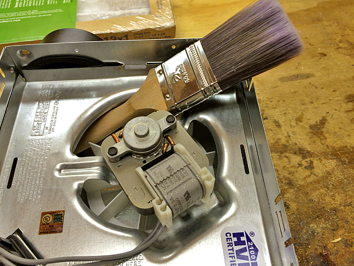 JUST KIDDING!!!! Ha ha ha....
Actually the fan motor (NuTone Model 696N) is an enclosed shaded pole, thermally protected, 120vAC, 60 Hz, .9 amp. design. I believe that given the travel distance the paint vapors will travel from the airbrush to the fan, via a filter, the potential for ignition with this fan motor is minimal. The real test will come when the motor's power is tested in the enclosed chamber to see if it is strong enough to maintain proper airflow out of the painting chamber. My initial calculations indicate that it will work. Chris A Trip to Home Depot for the Paint Booth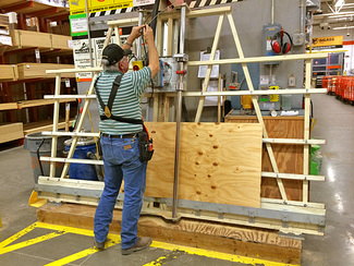 I have enlisted the assistance of my uncle, Joe Scorsone, for the airbrush paint booth project. We are going to stick closely to the original design, discussed earlier. One change will be to have the filter accessed through a door in the rear instead of through the internal panel with the louvers. This will allow that piece to be fixed in place. Yesterday we made a trip to the Roanoke Home Depot to acquire more supplies, including a 4x8 sheet of plywood cut to three 18"x30" strips, two 15"x30" strips, and one 15"x18" panel for the rear. There is enough material left over to fabricate the filter groove and supply shelves in the front. In addition lighting, wire, switches, and hinges were among the list of supplies. Many thanks to my uncle for accepting this challenge! Chris
Custom Airbrush Paint Booth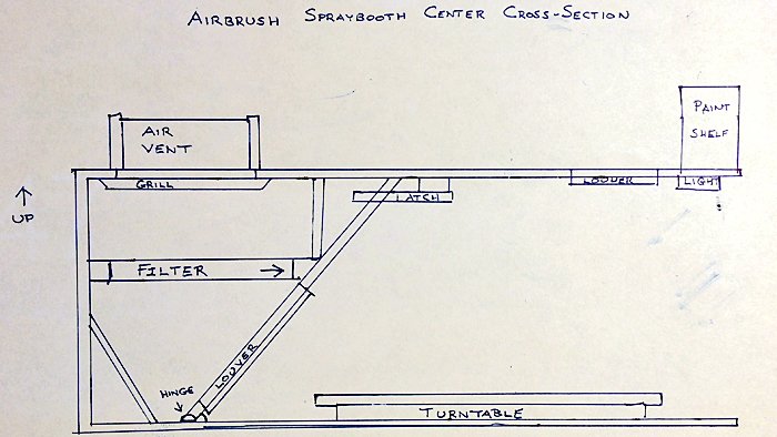 I have been very fortunate over the last two decades with my painting. By practicing the Rules of Paint the results have generally been excellent. My latest experience spraying a primer coat on two all-door boxcars has caused me to re-evaluate my processes. This review has resulted in my decision to build a quality airbrush paint booth! There are a number of how-to videos on-line that give some insight into how this project should be executed. Some of videos that I found to be useful are linked below. There are small paint booths available on-line, but they are a bit smaller than what I am looking for, and a bit pricey. 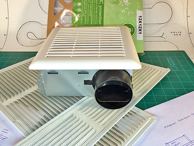 A wide variety of materials can be used to make these booths, some made from cardboard boxes and others from clear plastic storage containers. I will make mine out of wood as there are some features I want to build into it such as lighting, airbrush holders, and supply storage. While my son Jacob was at Velocity fitness training today I made a few rough sketches of my thoughts on the design for the paint booth. I had previously purchased a few of the components at Home Depot based on what I had learned from the videos. These supplies include a NuTone basic ventilation fan, a 12x12x1 air filter, and a couple of white undereave vents (one 16"x8" and one 16"x4"). 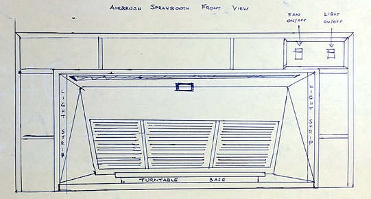 Focuses will be on user functionality and air flow. There will be a turntable, top and side lighting, air-flow to the bottom rear, paint and airbrush holders, and storage for painting and cleaning supplies. A separate component that will be sized to fit under and open window will be built to allow ventilation to the outside. This piece will be connected to the fan's exhaust via flexible dryer ducting. Introducing an airbrush paint booth to my painting process will allow me to paint indoors where I can have better control over the air temperature and humidity. Ultimately this protected environment will yield better paint job on my models!
Chris 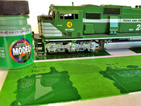 My earlier purchase of most of the Model Flex green paints available at Discount Model Trains confirmed what I had suspected, that the Katy Green would be the best starting point to begin the matching process. Painted swatches from all of the greens revealed that ALL of them were darker than the green on my Floquil painted locomotives. This meant that the first strategy would be to introduce metered amounts of white to the closest color--Katy Green. I would use a clear plastic paint dropper to add the drops of white paint. 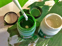 I found a sheet of Evergreen Styrene Plastic to use as my test bed to create color swatches. Using masking tape in a grid pattern each color swatch had a roughly equal area on the Styrene sheet. The first four test swatches had 3, 9, 18, and 27 drops of white added respectively. These were all very dark and had little visible variance. The next four test swatches had 41, 50, 60, and 70 drops of white added respectively. The color pattern was moving in the right direction but was not quite where it needed to be. The final four swatches had 85, 100, 115, and 130 drops of white added with the 130 swatch being very close to the green on T&GN SD60M 2493 used as the control in this process. 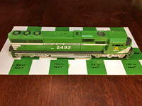 Given that each swatch painted depleted some of the green from the bottle, changing the drop/bottle ratio as white is added I suspect that an initial application of 150 drops of white paint to a new/full bottle of Katy Green paint will yield the correct color. 150 drops is right at 7 ml of fluid so the new formula for TGN/NTO green is 7 ml of Model Flex 16-02 Reefer White added to 1 oz (30 ml) bottle of Model Flex16-80 Katy Green. Now I need to master painting with this new paint. The challenge with the quick drying paint is to keep it from drying in the airbrush before painting of a model is complete! We will see... Model Flex Paint MatchingChris
Paint Experiment....Floquil to Badger Conversion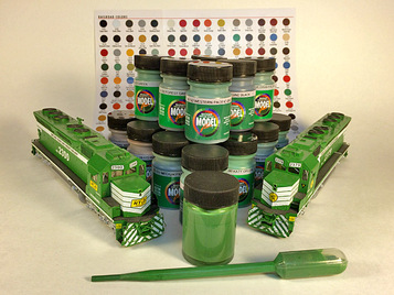 Referencing the dilemma mentioned previously about the demise of Floquil Paint, I have decided to search for a match to the green paint already used on T&GN and NT&O locomotives. The pros and cons of looking for a new scheme vs. maintaining the same have been considered and I have decided that practicing due diligence to find a match is best. Today I made a trip to Discount Model Trains in Addison, TX. Scalecoat II is my current brand of choice, however, Scalecoat II failed to obtain license for sale in the state of Texas and thus is not available for sale in local hobby shops. And that is too bad. The largest selection at Discount Model Trains is Badger Precision Design Model Flex brand. Several months earlier I had purchased a bottle of their Katy-Green (16-80) and Olive Drab-FSC (16-96) and had experimented with different mixes of the two. As it turns out the Katy Green by itself is not that far off from the original Floquil formula which was a 50/50 mix of MKT Green and Depot Olive. Determined that the right formula had to be somewhere in the bottles on the shelves in this store, I purchased about a dozen bottles of greens as well as a few other basic colors to experiment with. It is time to jump out of my comfort zone and learn to use a different brand and base of paint.... Chris
|
Categories
All
Author:
|
 RSS Feed


Proudly powered by Weebly
- - - Homepage of the Natchez Trace and Orient Railway and Texas and Great Northern Railway - HO Scale Meridian Speedway - Created by Christopher M. Palmieri - - -
© Christopher M. Palmieri - 1st Publish 12-10-2014
© Christopher M. Palmieri - 1st Publish 12-10-2014